Our first cruise to the Bahamas. We have worked hard to make Terrapin self sufficient living “off the grid” with watermaker, lithium batteries, more solar, and B&G electronics. We traveled about 1200 miles over this time and I’m happy to say that all our hard work paid off. The trip was fantastic and Terrapin and crew performed very well. We posted a lot to our Facebook page during the trip, but I failed to keep up the posting on this site. I will try to rectify that by posting some of our highlights here.
This is our actual Garmin In-Reach track
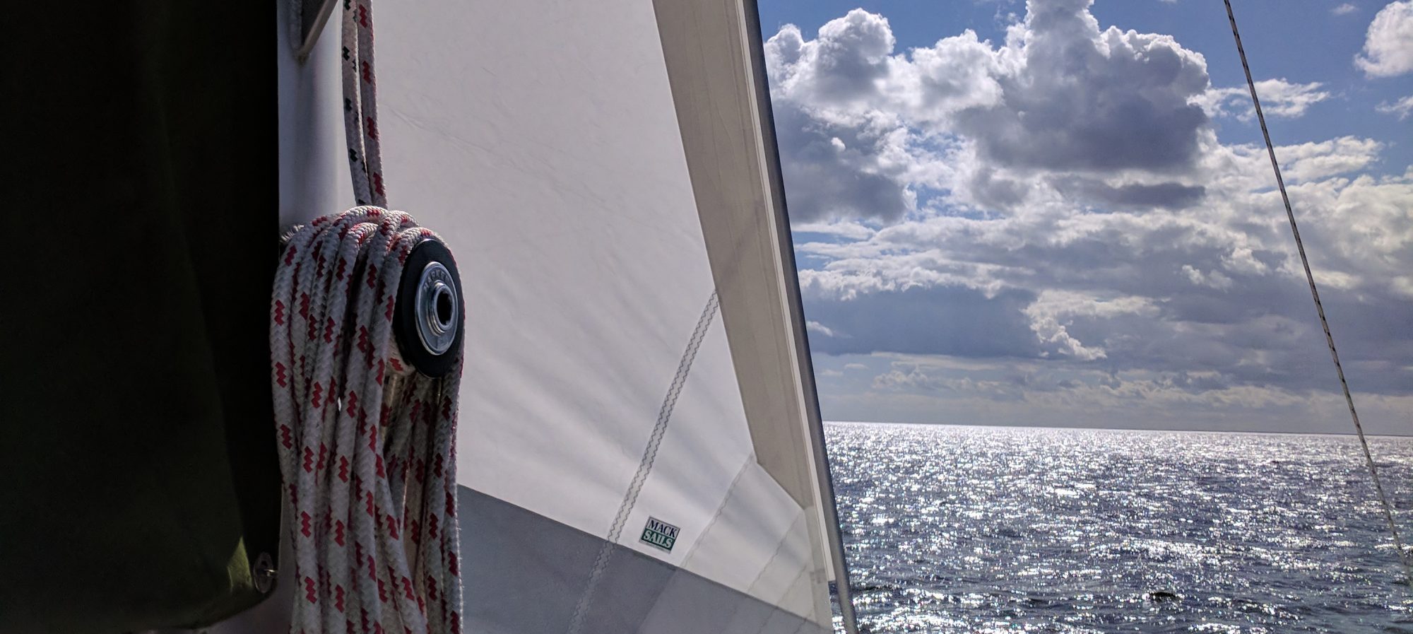
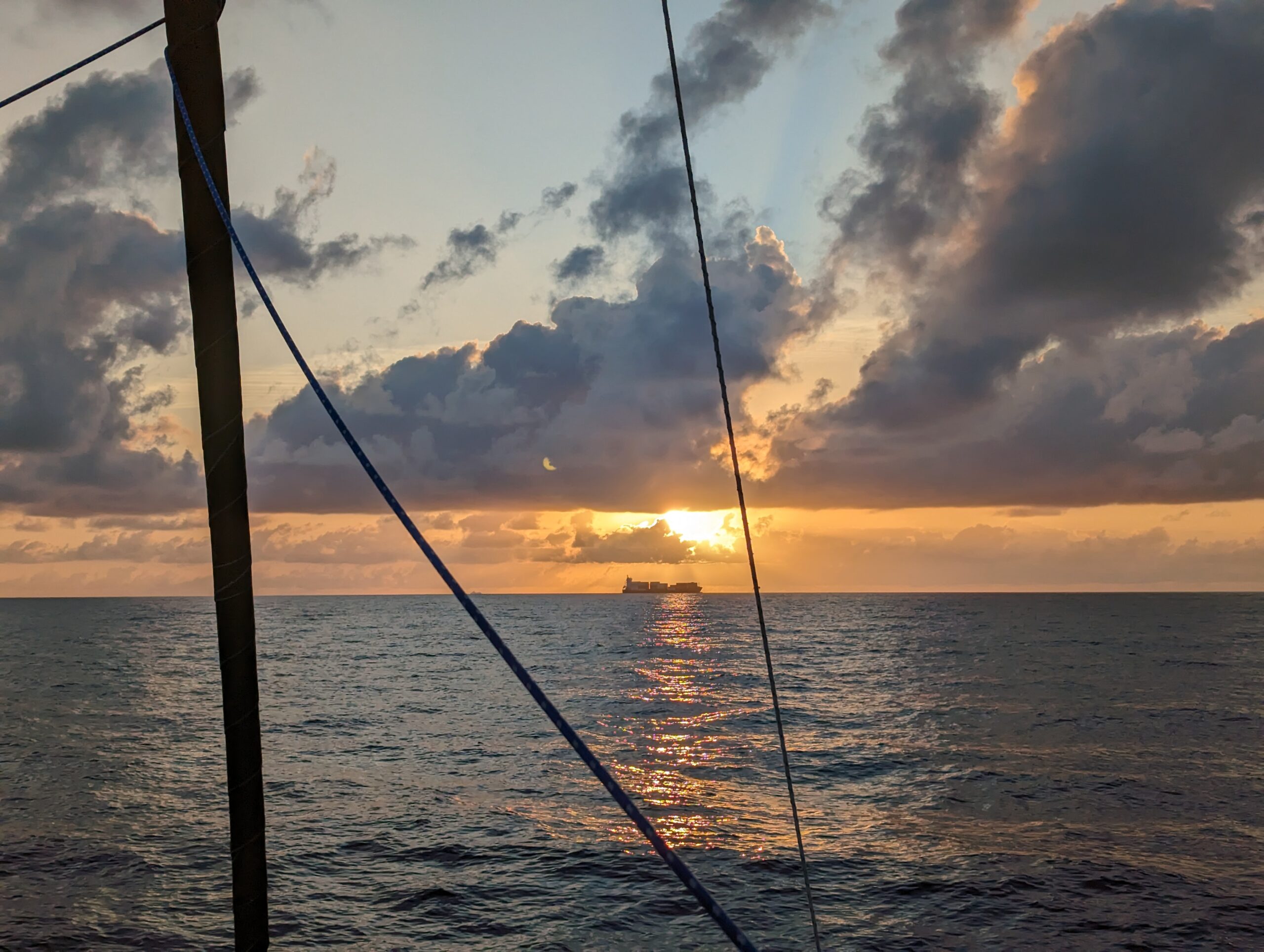
Crossing the Gulf Stream
Traversing the Gulf Stream. Notice the S-shaped track. This is due to the 2-3 knot Gulf Stream carrying the boat North as we kept a due East or West heading. Leaving from North Key Largo at sunrise, we arrived in Bimini late afternoon.
Crossing the Gulf Stream
Crossing the Gulf Stream at sunrise, this cruise ship was in our way!
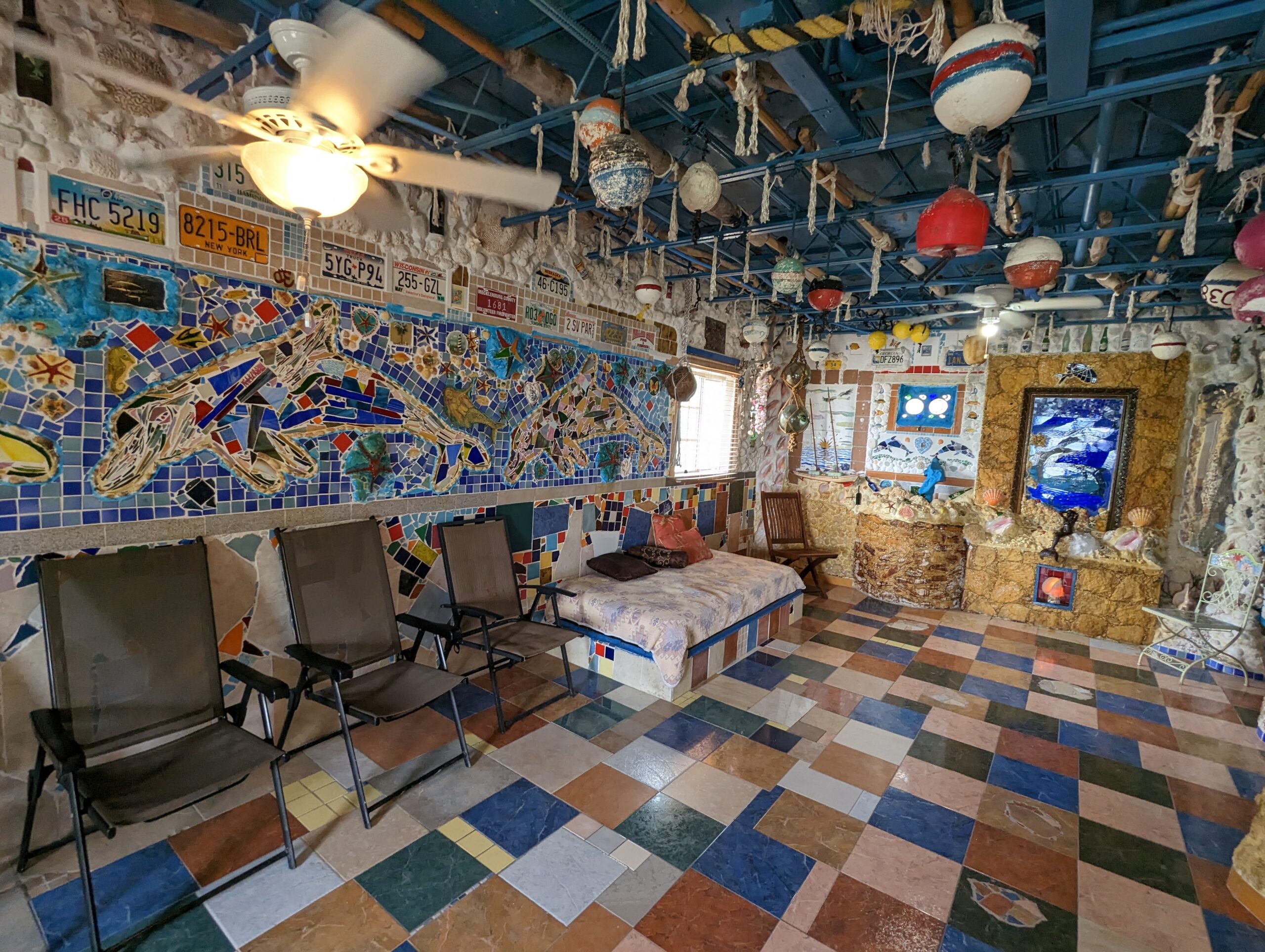
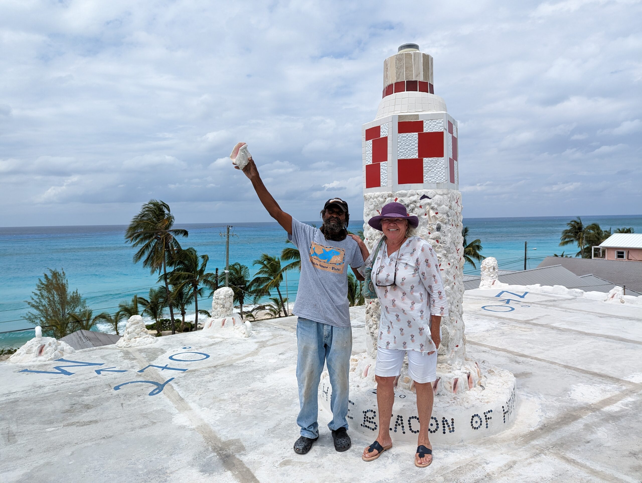
The Dolphin House
The absolute HIGHLIGHT of our visit in Bimini was the Dolphin House. It is a three story concrete building built by hand by Ashley Saunders. It is an absolute work of art.
Lighthouse at the top of the Dolphin House
Ashley Saunders gave us a personal tour of his Dolphin House, complete with a lighthouse on the roof!
We be good, mon!The Queen’s Bath, EleutheraGovernor’s Harbor, EleutheraTippy’s, on the Atlantic side of Governor’s HarborBells Cay, Exumas
Bells Cay is a private island in the Exuma Land and Sea Park. It is owned by Aga Khan, the Muslim Spiritual Leader and philanthropist. While we couldn’t go ashore, it provides one of the best sheltered anchorages from a strong West wind which blew for 3 days.
Water Spout, Exumas
Woke up to this water spout on my birthday. Luckily, the weather improved and we cruised into Staniel Cay to celebrate my birthday.
Back in the USA
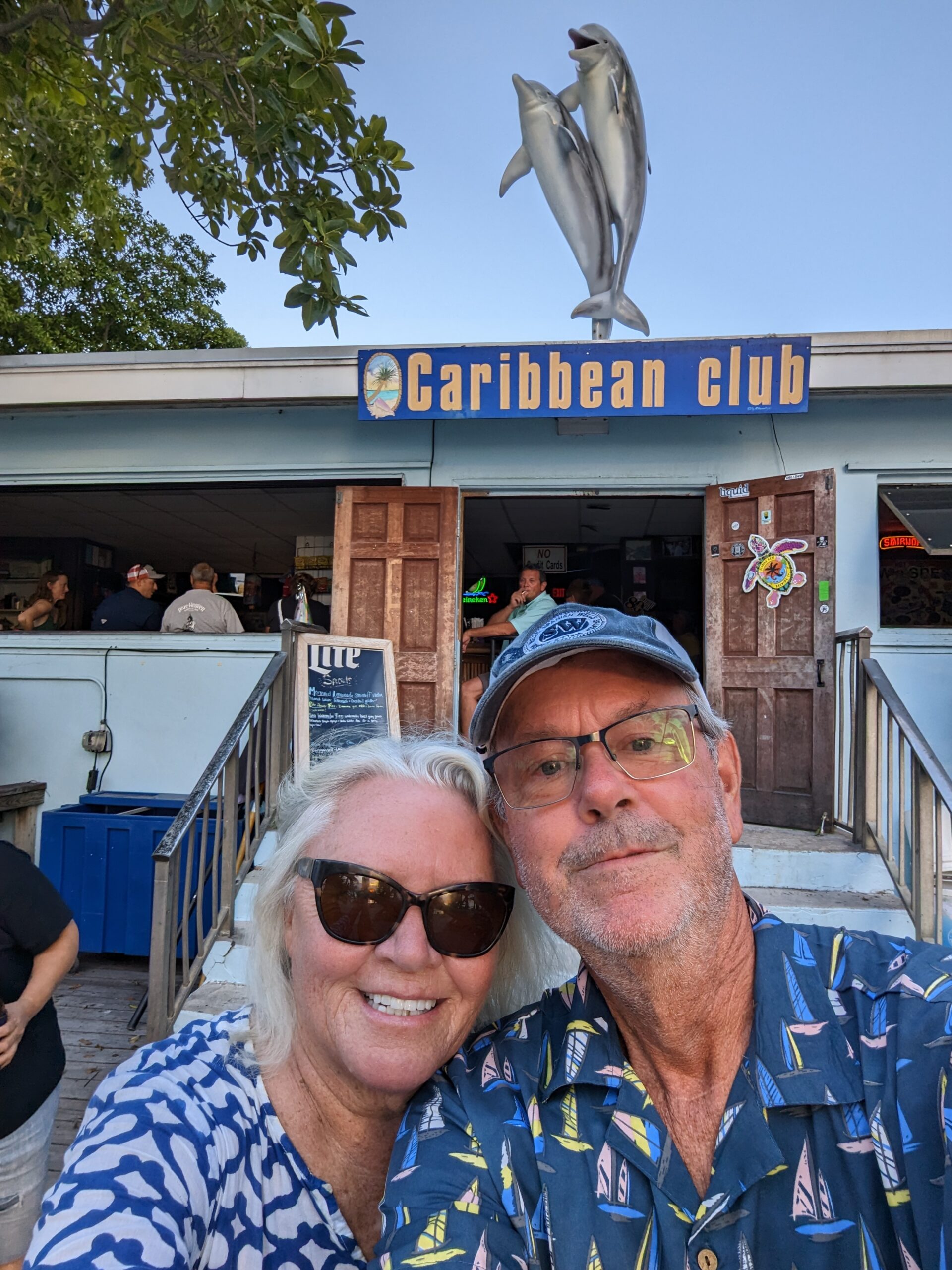
Our favorite bar in Key Largo where Bogart and Bacall stared in the movie Key Largo.
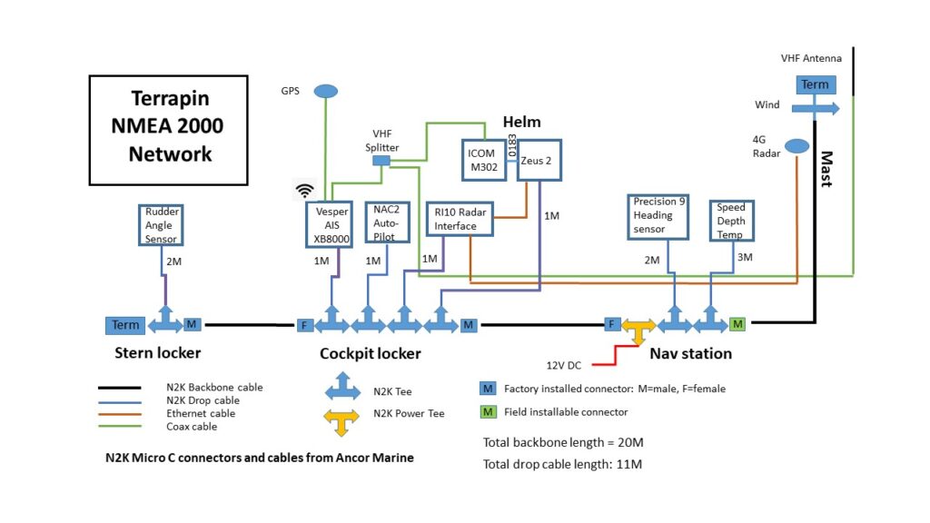
Otto is our third crewman. He steers the boat for us when we are not able to take the helm, for whatever reason. Otto is a computer that receives input from various sensors and then steers the boat based on criteria set by one of the human crew. We can tell Otto to steer to a particular compass heading. We can tell Otto to follow a particular route entered into the Zeus 2 chartplotter. We can tell Otto to keep the boat at a particular angle to the wind for optimum sailing. How does Otto do this? Otto is a B&G NAC2 computer linked to the Zeus 2 MFD via the N2K backbone for the control interface, and a motor that drives the steering wheel via a belt. Otto receives a variety of data from various sensors also connected to the N2K backbone. This includes wind speed/direction, compass heading from the Precision 9 compass, and rudder angle from the rudder angle sensor.
The Precision 9 compass is the key to allowing Otto to know which direction the boat is pointing. While we have a great gimballed compass at the helm, it is not electronic and does not provide any information to Otto. The Precision 9 is a fluxgate compass (electromagnetic) that provides heading and rate-of-turn information to the N2K network for use by the autopilot, radar and other algorithms within the Zeus2. It has an internal array of solid state sensors that can measure motion and orientation on 9 axes. So Otto always knows exactly which direction the boat is headed. To maintain a particular heading, Otto sends a command to the motor to turn the wheel, which is attached by a chain/cable mechanism to the boat’s twin rudders. However, Otto also needs to know which direction the rudders are pointing: straight ahead, 10 degrees to port, or some other direction. This is accomplished by a rudder angle sensor that I installed in the stern attached to the rudder control mechanism. The rudder angle information is then sent to the N2K backbone. Finally, we can also tell Otto to keep the boat at a particular angle relative to the wind. For this, Otto uses the wind direction information provided by the wind vane at the top of the mast through the N2K network. All of this can be controlled by the autopilot function on the Zeus 2 MFD. The autopilot is an essential piece of gear for any long distance cruising. It can get very tiring manually steering a course for hours at a time, and generally Otto can do it better. This allows the helmsman to keep a better watch or attend to other things like sail trim./
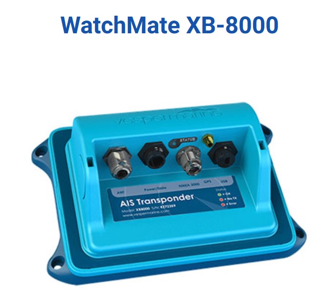
In phase 2 of my electronic system upgrade on Terrapin, I installed a Vesper XB8000 AIS transceiver. Automatic Identification System (AIS) is a means of broadcasting the location and information about a ship using VHF radio frequencies. It is used world-wide by commercial ships as well as recreational boats, and increasingly, other objects like buoys and personal locator beacons. However, there are a lot of boats that do not have an AIS transmitter, so you can’t rely on AIS to see all ships in your vicinity. It is nonetheless useful to see commercial ships and large yachts who typically broadcast AIS. If you want to see other vessels transmitting AIS, you only need a receiver, but if you want others to see you, you need a transceiver. AIS transmits vessel data such as name, size, type of vessel, speed, heading and the Maritime Mobile Service Identity number (think cell phone number for your boat). The really cool thing is that a vessel transmitting AIS data shows up as a little triangle on your chartplotter, so you can see exactly where it is relative to your own boat. If you put the cursor over the boat icon, you will see all the information about the boat. I was sold on AIS when we chartered a catamaran in the Caribbean that had AIS and I could “see” our friend’s boat from 5 miles away on the chartplotter as we rendezvoused. The AIS unit is basically a small device that can be mounted out of sight and connected to the N2K backbone with a drop cable. It also needs to be connected to a VHF antenna, preferably at the top of the mast, and an external GPS antenna. An AIS transceiver can also share the same VHF antenna as the VHF radio using a splitter. I chose the Vesper Marine AIS transceiver because it had a great reputation and it also had WiFi, so that the AIS data and N2K data could be transmitted to the WiFi system on Terrapin (See blog post How to Get WiFi on a boat). The Vesper AIS also has a great anchor watch app that will track the location of the boat during anchoring and alert you if the boat drags anchor.
Because of the importance of GPS for an AIS system, they are designed to have a dedicated input from a GPS “mushroom” antenna located in an outside area with a clear view of the sky. The vesper came with its own GPS antenna which I mounted on the stern rail and routed the coaxial cable to the inside locker where the AIS device is located. An added benefit is that this GPS antenna became the main GPS source for the Zeus chartplotter as well. Again, this illustrates the benefit of the N2K system. Because the AIS unit is attached to N2K, the chartplotter has access to not only the AIS data, but GPS data as well. The Zeus 2 chartplotter also has it’s own GPS antenna, but it is built into the chartplotter itself which is under the solid fiberglass bimini. It works, but it is not as sensitive as the dedicated AIS GPS.
The Vesper VHF splitter is a small device that allows the use of the same mast top VHF antenna for both the VHF radio and the AIS transceiver. It is a powered unit that has several great features and is well worth the expense. It actually amplifies the AIS signal and improves the sensitivity of the AIS. It also gives the VHF radio priority and maintains an antenna connection for the VHF radio even when power to the splitter is off. The splitter also has indicator LEDs that indicate whether the AIS or the VHF is transmitting and a red LED to warn if there is a problem with the antenna circuit. Hookup was easy. I removed the VHF antenna cable from the VHF radio and attached it to the Antenna Out on the splitter. The VHF radio was then attached to the splitter “VHF IN” connector and the AIS unit was attached to the splitter via the “AIS IN” connector. The splitter than needs to be connected to a 12Vdc source, switched on the same breaker as the AIS unit itself. This is important because the AIS can be damaged if it tries to transmit without an antenna connected.
Initial configuration of the Vesper XB8000 was a little bit convoluted but not too bad if you follow the directions in the on-line manual. Basically it involves downloading a configuration utility onto a laptop or ipad and connecting to the Vesper AIS directly with a USB cable. Once I did this, I was able to update the firmware, and configure the WiFi to connect to the Terrapin WiFi router. I then installed the Watchmate app on my smartphone and was also able to see AIS data and use a very good anchor watch program.
Last but not least, the AIS unit was easily attached to the N2K network with a short drop cable and tee. When I powered up the Zeus chartplotter I was able to see AIS targets all around my area, very cool! In the settings menu, the Zeus chartplotter also recognized the GPS antenna connected to the AIS unit and asked which GPS I wanted to use: the Vesper or the Zeus. For reasons described above, I chose the Vesper GPS.
The Vesper Marine AIS installed on Terrapin has been working flawlessly now for three seasons. Most boats in my sailing area, south-west Florida, do not have AIS so it is not particularly useful for collision avoidance or tracking other boats. However, as I cruise in areas with more commercial traffic, I will be glad to be able to see these ships. I believe there are a lot more recreational vessels that have AIS receivers because many VHF radios now have built-in AIS receivers. In this case, many more vessels will be able to see me. In one situation, we were following friends on another boat to one of their favorite anchorages off Boca Grande. Since they were a power boat, they got ahead of us and we lost sight of each other. However, they could easily see us on AIS and gave us a few course alterations as we approached.
When I bought Terrapin in 2017, she had original equipment (1997) gauges based on the 0183 protocol and didn’t even have a wind speed/direction sensor at the top of the mast. The electronics consisted of original equipment Raymarine speed/depth transducer, autopilot, and an old Garmin GPS chartplotter. Over the ensuing three years I have completely re-done the electronics and installed an N2K network. The only thing I really wanted/needed at the time was wind speed/direction at the top of the mast. Terrapin is a sailboat after all, and knowing wind speed/direction is pretty important. As I started doing research on mast-top wind sensors, it became apparent that N2K was the way to go. Even if I didn’t do everything at once, N2K would allow me to add new instruments and sensors at a later point. Of course, in order to see the wind speed/direction display, I would need a new display and I decided on the B&G Zeus 2 multi-function display (MFD).
If you have spent any time reading about or using boat electronics, you are probably well aware of NMEA 2000. In a nutshell, NMEA 2000, abbreviated to NMEA2K or N2K and standardized as IEC 61162-3, is a plug-and-play communications standard used for connecting marine sensors and display units within ships and boats. Physically, it consists of a “backbone” cable capable of transferring data and small current, kind of like USB, and way of connecting all sorts of sensors and instruments to the cable through tee connectors and drop cables, all using an industry standard connection plug and data packet protocol. N2K has been around for about 20 years, but there are still a lot of boats with pre-N2K electronics based on the old NMEA 0183 protocol. As these electronics begin to fail, the owner will need to consider adopting an N2K system. You don’t have to replace everything as 0183 instruments can work with N2K using 3rd party adaptors.
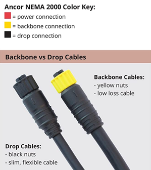
Backbone vs drop cables, Ancor Marine
N2K power tee, Ancor Marine
N2K tee, Ancor Marine
An N2K system is very much a DIY project for a boatowner as long as you do some reading and follow some basic rules. The main components of the N2K network are the backbone cable, tees and drop cables going to each instrument/sensor, a specialized power tee to provide low amperage 12V power to the network, and a terminator at each end of the backbone. The length of the backbone is limited to about 100m while each drop cable is limited to about 5m or 16 feet. This basic backbone can be hooked up to a multi-function display, individual displays, a laptop, or even WiFi using appropriate adaptors. It is easily adaptable to both small and large boats. Because the network is energized with 12Vdc, many devices, particularly low amperage sensors, do not need to be wired separately to 12V. The N2K drop cable provides all the power they need. Other devices that require additional current to operate, like autopilots, displays, and AIS, will need to be wired separately to a 12V source in addition to the drop cable. N2K is not particularly high bandwidth and is not designed for transmission of radar or video. One other important consideration in designing an N2K system is that there are male and female connectors. Each section of drop cable will have one male and one female connector at either end. Likewise with tee connectors. The straight line part of the tee is designed to attach to the backbone, one male and one female end. Thus, the length of the backbone is directional. The right angle part of the tee is designed to attach to a drop cable and is female. Terminators are either male or female.
N2K female (top) and male (bottom)
I started the N2K installation on Terrapin with the purchase of the B&G 508 wind sensor. This sensor actually came bundled with 20m of N2K backbone cable and included a terminator. Because of the length limitations of the drop cable, the backbone must start at the top of the mast if you want to attach mast mounted instruments to your N2K network. Thus, the wind instrument at the top of the mast became the first instrument attached to the backbone. Running the backbone cable down the mast was the most difficult part of the whole installation and I had two pros doing it while they were rigging my new roller furling! The backbone should then be routed through the boat such that every instrument or sensor that you might want to ever attach to the backbone is no further than 16 feet from backbone cable. It is best if you can identify a few zones where groups of tees can be attached. In my installation, there were obvious zones at the nav station behind the breaker panel, a locker below the cockpit, and a locker near the stern.
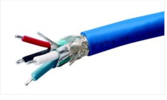
N2K cable
The one mistake I made in designing my N2K system was that I used the single 20m backbone supplied with the wind sensor for entire length of the N2K backbone. This meant that I had to cut the cable twice to insert tees at two of the zones. This required the installation of four N2K connectors. This didn’t seem to be a problem because you can buy “field attachable connectors” from a few different suppliers. I bought the ones sold by Maretron. They make it seem easy to do the attachment but, believe me, it is not! The N2K cable contains 4 insulated wires, one non-insulated wire and a metal sheath, all of which need to be connected to little screws within the connector. To make matters worse, the non-insulated wire needs to be insulated with a tiny length of heat shrink tubing so it doesn’t short out on the other terminals.
The rigger installed the wind sensor at the top of the mast and then fed the N2K backbone down the mast into the cabin using a messenger wire. Even without a connector, the cable was difficult to feed through a narrow spot at the deck. I then pulled the entire 20m of cable down through the mast and routed it through the starboard side of the boat, through the nav station and back to the stern. I then cut the backbone at the locations where I needed tees and set about attaching the field attachable connectors. This was difficult and time consuming and, as I was to find out later, I obviously messed up at least one connector because the network didn’t work.
Next, I connected the power tee and wired it to the Instruments breaker at the nav station. Then I installed a tee in the locker by the cockpit helm and fed a drop cable to my new Zeus 2 MFD. The Zeus 2 was also wired to 12Vdc per the instructions. One of the great things about the Zeus is that it has a built in Network Analyzer, and it was immediately apparent that there was a problem with the N2K network. Since I was not very confident in my field attachable connectors, I suspected these were the cause of the problem. I decided to replace these sections of backbone with shorter cables with factory installed connectors. I purchased these cables as well as extra tees through Ancor Marine. This left my network with only a single field attachable connector at the end of the section of backbone that was routed through the mast. This one was apparently a good connection because the network worked fine once I made this change.
At this point, I had a working N2K network with only wind speed/direction and a Zeus 2 MFD, but with the ability to add devices and sensors as desired. I sailed Terrapin for a season with this setup and got familiar with using the Zeus chartplotter with its great SailSteer wind display. Over the next two sailing seasons, I added a Vesper AIS transponder, a B&G autopilot, B&G 4G Radar, and a B&G depth/speed/temp transducer. For each addition, all I had to do was to add a tee, or multiple tees in the case of the autopilot, to the backbone cable and install the instruments. In each case, the Zeus immediately recognized the added device and also provided the interface to perform calibrations and set other options for each device. While it is possible to mix and match brands on the N2K network, there are also proprietary signals sent through the N2K network and I believe this is why my B&G system worked so seamlessly. That being said, I do have one non-B&G device, the Vesper AIS transponder, and that also works flawlessly.
In summary, when designing your N2K network, first decide the locations in the boat where you will need one or more tees and then purchase separate lengths of backbone with factory installed connectors. You might need to remove a connector to route the cable through the mast or a tight channel, necessitating the installation of a field attachable connector, but try to minimize this. Connect the sections of backbone with one or more tees, provide 12V DC to the power tee, and add a terminator to each end. Finally, a good MFD like the B&G Zeus to tie everything together is one of the best ways to set up your network.
The Zeus 2 Multifunction display. Current display is showing windows for the autopilot (left), chartplotter (middle) and SailSteer (right). The chartplotter shows the location of Terrapin (black boat shape) and also other vessels broadcasting an AIS signal (open triangle).
For the helm and the brains of the system, I installed the highly rated B&G Zeus 2 MFD. It comes in 7”, 9” and 12” and I chose the 9” display because it fit perfectly at the helm. These MFDs have the capability to customize windows to display virtually any data present on the N2K system. The most important display is the chartplotter, which shows a nautical chart with your GPS location and the ability to zoom in and out. If you add radar to the system, it will overlay the radar on the chart so you can see exactly what is around you relative to charted objects. If you add an AIS receiver, you can view other ships on the chartplotter that are broadcasting AIS information. The MFD also has a sophisticated control system to run the autopilot and to set navigation routes. The B&G Zeus also has a great panel called SailSteer with key sailing data including vessel heading, wind direction (apparent and true), wind speed (apparent and true), GPS course over ground, speed over ground, etc. There is a ton more that these MFDs can do, but you get the idea.
In the Spring of 2019, I spent about 7 days upgrading the battery and charging system of Terrapin. For those wishing to do something similar, I have written a detailed description of my upgrade. Although I have a good foundation knowledge of basic electrical circuits, I needed to familiarize myself with marine electrical systems, particularly as they relate to the cruising sailboat. While there is no one right way to wire a boat, I was able to focus on a series of best-practices that allowed me to design a good charging system.
My main sources were:
The Boat Owners Mechanical and Electrical Manual, by Nigel Calder
A great web site operated by Rod Collins at Compass Marine
I actually purchased my Balmar alternator and regulator from Compass Marine. Customer service was great. He gave me great advice prior to purchase to make sure I got the right alternator/regulator combination for my needs and provided help during my installation.
Goals:
My goal was simple: to create a battery and charging system that would sustain long term cruising away from the dock. To do this, I also carefully considered the charging needs of Terrapin, the existing systems and the typical electrical usage of the crew (Laura and I, and the occasional guests).
Existing equipment:
House battery bank: 4 6-volt deep cycle lead acid batteries, 216 AH each, wired in series/parallel to produce a 12V bank of 432AH.
Two stock Hitachi Alternators, internally regulated, 50A.
A Powerline battery isolator
Two engine starting batteries, 12V automotive cranking batteries.
Solar panel, 150W, PWM controller
Air X wind generator
A Freedom 20 battery charger from Heart Interface
New equipment installed:
Balmar 6 series Alternator, 120A, including MC614 regulator and serpentine belt kit.
Victron Battery monitor, BMV 712 Smart.
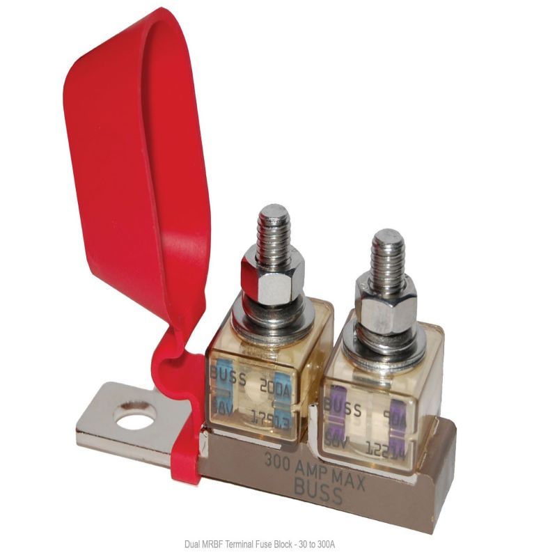
Fusing: Blue Sea MRBF terminal fuse blocks
Xantrex Echo charger for the start battery
Tools: FTZ Battery Lug Crimp tool and FTZ battery lugs.
Blue Sea fuses
Victron BMV 712
Balmar alternator
Crimper
This was not a complete re-do as most of the existing components and charging systems worked, and the batteries themselves were in good shape. This was also phase 1 of an anticipated two-phase upgrade. The main aspect of phase I was an alternator upgrade and a re-wiring of the battery and charging system. This was made a little more complicated in that Terrapin (a catamaran) has two inboard diesel engines, two alternators, two starters, two starting batteries and a four-battery house bank. The house bank were relatively new deep cycle lead acid golf cart batteries.
Many would argue that it is better to upgrade to as much solar as possible and that it is inefficient to run the engines solely to charge the batteries. I agree, but Terrapin is a small cat and there is limited room for additional solar. My existing panel is at the stern, above the dinghy davits. There is room for additional panels on the coach roof, but part of that area is always in shade due to the boom and the stack-pack, or the main sail if it is up. Nevertheless, I do plan to add a panel up there. While I don’t plan on routinely using my engines solely to charge the batteries, I am usually running the engines at least an hour or two every day while cruising, usually to get in and out of an anchorage. Of course, if there is little wind, then I run the engines a considerable amount more. Thus, a high output alternator makes sense to make sure the batteries get as much charging as possible when motoring.
Based on all my reading, my specific goals were as follows:
Upgrade one of the alternators to a high capacity alternator with an external regulator.
Run all charging to the house bank: both alternators, solar panel, wind generator, shore power battery charger/inverter.
Get rid of one of the start batteries and wire the one start battery to both starting motors of the engines.
Add an echo charger to keep the start battery charged.
Re-wire the battery switches to allow engines to be started from either the house or start battery, and allow power usage from either battery. With this set-up, the start battery essentially becomes an emergency battery, normally isolated from house loads, but accessible if needed.
The lead acid (LA) battery was invented in 1859 and represents the earliest type of rechargeable battery still in widespread use. In the boating community, the lead acid battery still dominates but they are slowly being replaced by lithium ion, specifically lithium iron phosphate (LFP) batteries. The type of LA batteries that serve has the house storage bank for boats is very different from your typical car battery. They are referred to as deep cycle batteries and are designed for repeated discharging and charging. The most popular batteries for this purpose and the batteries we have on Terrapin are 6V golf-cart batteries, wired in series to produce 12V.
The LA batteries work well if you take care of them, but they have several limitations. They are very heavy, the usable current is only 30-40% of the total amp-hour capacity, they are take a long time to charge to full capacity and they have to be topped off with water periodically. LFP batteries overcome these limitations making them a much better option on a sailboat, but they are considerably more expensive. Because my bank is in good shape, I decided not to go with LFP yet. That will be phase 2.
When away from the dock, the amount of charging available on a boat is often limited. In brief, the number of amps removed x the number of hours (amp-hours) must be replaced by charging. On top of that, as the battery gets to about 80% charged, it begins to accept less current (amps) making it harder and taking much longer for that last 20% of charge. As a result, many LA batteries on boats never get fully charged, and die an early death.
The charging systems on Terrapin consist of 2 alternators, one on each engine, a solar panel and a wind generator. There is also a Honda suitcase generator that can be plugged into the boat’s “shore power” inlet. Of course, when at the dock, the shore power is plugged in and the boat’s AC/DC converter (Xantrex Freedom 20) charges the batteries to the max. After two seasons on Terrapin with prolonged time away from the dock, I realized my charging system was not adequate to keep the batteries fully charged. The solution was to fire up the Honda generator every three days or so and run it for a couple of hours to get the batteries fully charged. The solar and wind generator helped, but were not sufficient to supply the current needed. I could add additional solar panels, but I simply don’t have the space on Terrapin to install the amount of solar needed to be fully self-sufficient. That leaves the alternators. The stock alternators on Terrapin were automotive alternators driven by 18hp diesels. These alternators were designed to supply small amounts of charge to a car battery after it starts the car. This is inadequate to charge deep cycle batteries. So, I decided to replace one of the alternators with a marine rated high output alternator, along with an external regulator to put out the voltage required for good battery charging. Yes, Terrapin is a sailboat, but when out sailing, we are often running the engines 1-2 hours a day just to move the boat in and out of harbors or longer when the wind dies. So, the alternators should be able to handle the full charging needs of the house battery bank. Finally, there were two starting batteries dedicated to starting the diesel engines. These batteries were wired in a confusing way and shared charging sources with the house bank.
Once I decided to upgrade the alternator, it became apparent that the wiring needed changing to make the charging more efficient, and take advantage of new technology.
Before
The original configuration consisted of 4 6V deep cycle golf cart batteries, two in series and then paralleled to get 12v at 430AH, a pretty standard battery configuration. However, the heavy cables connected to the bank were at the wrong positions. They worked, but were not optimal to deliver equal charging or equal loads on all 4 batteries. There were two 12v start batteries with a complicated mix of switches connected to the starters as well as the alternators. There were two stock Hitachi alternators (55A) connected to the house and start batteries via a Powerline diode battery isolator. This resulted in very poor battery charging from the alternators because the battery isolator had a significant voltage drop (see the Compass Marine web site for a good description of the limitations of diode battery isolators and voltage drop). The result was that the house bank never got fully charged when I was motoring, even for long periods of time. There was one 150W solar panel and a wind generator that charged the house bank directly. The fusing was inadequate and located in a very inaccessible place. The fuses were also original equipment (20 years old) and I didn’t trust them.
After
The upgrade consisted of installing a Balmar 6 series alternator, (120A) and an MC 614 external programmable regulator on the starboard engine along with a serpentine belt kit. I removed the Powerline battery isolator and rewired everything so that all charging went to the house bank, including both alternators. Just because there are two engines does not mean one needs two starting batteries. Starting an engine uses very little of the battery capacity, so a single start battery is all that is needed. I removed one of the start batteries and gave it to Gary down the dock. This also removed about 75lbs of weight from Terrapin.
Another important feature of a good battery and charging system is a battery monitor. I selected a Victron battery monitor. The basic concept is that there is a shunt between the negative battery post and all ground connections to the house bank, whether charging or load. The battery monitor then detects all current running either into or out of the house bank. It also directly senses the battery voltage right at the battery terminals. All of this information is displayed on a small display inside near the fuse panel. I can also connect with my smartphone via Bluetooth and read the information on an app. The original panel on Terrapin has an analog system that attempts to do the same thing, but it is not very accurate and does not keep track of the current in and out. Why is this so important? Consider a day on the boat, out sailing, away from the dock. There will be several loads draining the house bank as well as sources of charging. The refrigerator, nav system, autopilot, WiFi, and various gadgets being charged will all remove amps from the batteries. At the same time, the batteries will be charging from the solar panels, wind generator and alternators if the engines are running. At the end of the day, it is impossible to know the net amp-hours delivered or removed from the house bank. The Victron monitor keeps track of amps-in and amps-out and will give a picture of how discharged or charged the house bank is. Of course it will also tell you the battery voltage, but that is not a very good way of determining state of charge. It also allows one to know at a glance how efficiently the batteries are being charged from, say, the alternators.
If all the charging is now directed to the house bank, how do I charge the single start battery, you ask? This is accomplished with a nifty little device called an Echo Charger. Echo Chargers are good if the battery being charged does not need high amperage charging, like a start battery. After starting two engines, the start battery is only slightly discharged and doesn’t require huge charging currents. The echo charger puts a max of 15 amps into the start battery only if it senses a charging current is available. The advantage here is that it does not require a heavy cable, only a 12-14 AWG wire. The echo charger also has circuitry to prevent over charging of the battery.
Then there is the issue of how to wire the switches to give maximum flexibility to start the engines from either the house or start battery, or to run the various loads from either battery, or isolate either battery in the event that a battery develops a short. After doing a lot of reading, I settled on an ingenious and simple switch arrangement that accomplishes these goals.
To do all this, I bought a large long handled FTZ battery lug crimp tool needed to crimp the lugs on heavy 2/0 battery cable. This way I was able to make my own battery cables and do a neat re-wiring job. I was able to re-use two of the battery switches from the old set up. Fuse options have come a long way in the last 20 years, and there are now many configurations to provide fusing right at the battery post, or blade fuse configurations for smaller wiring. I used several terminal fuse blocks and some blade terminal fuses from Blue Sea Systems.
Since a picture is worth a thousand words, here is the final wiring diagram I ended up with.
In practice, the system works very well. To gauge the charging status of the batteries, I check the Victron Battery monitor frequently. It will tell you the voltage of the house battery bank, or the starter battery. The voltage should be in the range of 12.4 to 13.8 volts. This doesn’t tell you the actual voltage of the battery because the voltage will vary depending on the charging or load on the system. The other thing to look at is the amps going in or out of the system. Finally, the monitor will tell you how much the battery bank was charged or discharged since the last time it was fully charged. The monitor is not smart, so it can provide misleading information on the state of charge of the battery, so the user needs to do the thinking. A fully charged battery that has rested for a while, will show a voltage of about 12.8 volts. It will also not take much current if you supply a charging source. As you are drawing down the charge, keep an eye on the monitor and check it in the morning. The battery voltage should never get below 12.1 volts. Finally, you can check how many net amp-hours you have used in, say, a 24 hour period, i.e. the amps-in minus the amps-out. This will give you an idea of how many amps you need to return to the battery bank the next day.
Let’s say you see a net loss of 100 AH when you get up in the morning. As the bank is charging the next day, keep an eye on the amps going into the bank. Early in the day, the amps being delivered (if the engines are running) will be between 75 and 100 amps. Over time, the amps being accepted by the bank will decline as they become more and more charged. When the monitor shows that 100 AH have been returned to the bank, it is fully charged, more or less.
The starter battery is typically isolated from the loads, so that it will never be run down if a load is accidentally left on. It is also isolated from the charging sources, all except the echo charger. So, the start battery should always read 12.8-13.8 volts if it is healthy. However, the switch arrangement allows one to start the engines from either battery bank, or run the house loads from either bank.
Below is a description of the use of the house battery bank/start battery switches.
House 1-2-Both switch
Start On-Off switch
Switch position
Start House
On 1
This is the normal operating position. House and start batteries are separate. All charging goes to house. The start battery only receives charging from the echo charger. The only load on the start battery are the starter motors.
Off 1
Use this position if you want to cut off the voltage to the starter motors or to work on the engine (see below for additional precautions). Start battery is isolated. House bank and start battery will receive charging. Engines will not start.
On 2
Use this position if the house bank is dead or shorted out, and you need emergency power, e.g. for nav instruments. The house bank is disconnected from load and the start battery is directly connected to both load and charge (except for the Balmar Alt). The starter battery will receive charging from the port alternator, solar and wind, so this should get you home if the house bank fails. Beware that the start battery has low capacity.
Off 2
There is no good reason to use these switch positions unless trouble shooting the system. Both the house bank and start battery will be disconnected from the loads and most charging except the Balmar.
On Both
Use this position if the starter battery is weak or dead and you want to start the engines using the house bank. This can also be used to “equalize” the start battery using shore power, or to provide extra charging to the start battery from the Balmar alternator. This attaches a “jumper” between house and start. The start will receive charging from all sources, but will also be contributing current, along with the house bank, to all loads. House bank will contribute current to the starters.
Off Both
Use this if the starter battery is dead or shorted out and you need to start the engines. This attaches a jumper between house bank and the starter motors, so that the engines will start from the house batteries.
Off Off
Use this position when leaving the boat for extended periods. This will isolate the house bank from any potential battery drain from the house panel, and the start battery from any potential drain, e.g. from a shorted starter motor. However, the house bank will still be connected to the Balmar alternator, solar panel and wind charger. So the house bank will continue to be charged by the solar panel and the start battery will still receive charging from the echo charger. There will be no power to the house electrical unless the boat is plugged into shore power.
Note:
There is currently no way to isolate the Balmar alternator from the house battery bank. I will be installing an Alternator Service switch in the engine bay for this purpose. In the meantime, to work on the either engine, disconnect the negative cable at the Victron shunt near the battery bank, and turn the starter battery switch to off. This will prevent an accidental short at the alternator, or the starter motor.
Water, water, everywhere, And all the boards did shrink; Water, water, everywhere, Nor any drop to drink.
From The Ancient Mariner
November, 2018
The Ancient Mariner had to haul his own water, but thanks to modern technology, we can now convert salt water to fresh water on a sailboat. To me, a watermaker is freedom. Freedom to cruise for extended periods of time without having to worry about pulling into a marina or fuel dock for water. Freedom to take showers and rinse salt off of the boat and equipment without worrying about running out of water. Terrapin is a small catamaran with a modest capacity water tank of 47 gallons. This means that a full tank of water will last the two of us about 3 days of conservative water use: dishes, short showers, stern shower rinse after swimming. Why not carry extra jerry cans of water lashed to the stanchions? In a word, weight. At about 8.3 pounds per gallon, we would have to carry about 370 pounds of water just to double our capacity, not to mention having 6 jerry cans tied around the deck. Catamaran performance is seriously impacted by weight and 370 pounds is a lot. Then there is the fun of carrying around 50 pound jerry cans on the deck of a sailboat, and sometimes in and out of a dinghy. Finally, in some isolated areas as in the Bahamas or Caribbean good quality water is hard to come by. So, for a small boat, and in particular catamarans, watermakers make a lot of sense.
But then there is the issue of how to power it. The heart of a watermaker is a high pressure pump that can put out 800 psi of pressure, and then a low pressure pump to supply sea water to the high pressure pump. Both of these pumps draw a lot of power. There are two flavors of watermakers: AC and DC. AC watermakers can put out more capacity in terms of gallons per hour, but draw more power. This AC power generally has to be provided by an on board generator. DC watermakers use less power but don’t put out as much capacity. The advantage of the DC watermaker is that they can be powered by solar if you have sufficient solar capacity.
Terrapin has 140 watts of solar, not enough to power a high output DC watermaker and it would be difficult to add more solar (although I am still considering it). We do however carry a Honda EU2000 suitcase generator that fits in the stern locker. This generator can power an AC watermaker. Watermakers are also noisy and I wanted the highest capacity possible to limit run time. In terms of capacity, AC watermakers win hands-down.
My choice:
Cruise RO makes highly rated AC watermakers, the most popular of which can be powered by the Honda 2000 generator and puts out 30 gallons per hour. Most comparable DC watermakers put out less than half that much. The other strong selling point for the Cruise RO is that it is made up of readily available pumps and filters so when components inevitably need replacing, they are easier to source and less expensive. Finally, the owner of the company, Rich Boren has earned a reputation for outstanding customer service. At about $6,000, this is not a decision to make lightly and I believe I did my homework.
How they work:
Most watermakers are modular and require custom, permanent installation on the boat, although one that I considered, the Rainman, is portable and self contained in two suitcases. The heart of the watermaker is the reverse osmosis membrane. This membrane basically filters out the Na+ and Cl- ions and anything else out of salt water and only allows H2O to pass through. Of course to do this, the water has to be under tremendous pressure (800 psi) to force it through the membrane. This is accomplished with a high pressure pump. The membranes are rolled up in a 4’ tube capable of withstanding this pressure. The number of tubes dictates how much fresh water can be produced. My Cruise RO has two pressure vessels. The high pressure pump needs to be supplied a continuous supply of clean seawater, and this is accomplished with a low pressure pump and some pre-filters. All of this is attached together with a bunch of tubing and valves. On top of all this, some watermakers add in electronics and sensors to make it all run automatically and shut off when done. This greatly increases the cost and adds to the complexity, which means less reliability. In my opinion, watermakers are not a “set and forget” device and should be monitored while operating. With two high wattage pumps and 800 psi of pressure, what could possibly go wrong? The cruise RO has an electronic option, but I did not go with it and Rich does not even recommend it for most people.
My installation:
The biggest decision is where to locate the various components on the boat. I chose the head (forward in the starboard hull of the PDQ 32) to locate the valve panel as there is a large flat bulkhead to mount the panel. Furthermore, behind the panel is the forward bow locker with enough space for all the tubing, pre-filters and pumps. I chose to locate the high pressure vessels under the forward settee in the salon. This will allow easy removal when the filters eventually need replacing. Another decision to make is how to supply the watermaker with a supply of sea water. This requires a thru-hull below the waterline. The PDQ 32 has a thru hull in the forward bow locker, but it was supplying sea water to the head, a common Jabsco head with a manual pump. The watermaker requires a dedicated through hull and I couldn’t simply put a tee in the line to supply water to both the head and the watermaker. But then I thought, why flush the toilet with sea water when I will have a good supply of fresh water? Sea water to flush the toilet is problematic in that the sea water itself in the bowl and lines begin to smell like sulfur if allowed to sit for any length of time, and sea water in the holding tank makes the smell all that much worse. My initial thought was to install a new electric head that flushes with fresh water. I may still do that, but for now, all we need to do is add fresh water from the sink to the bowl using a cup, and then pump the head like usual.
The hardest part of the installation was getting the courage to cut two 12” square openings in the bulkhead. After consulting some knowledgeable folk, the consensus was this would not appreciably compromise the structural integrity of the PDQ 32. So, I went ahead. It was a matter of carefully locating all the components to make sure they were in logical and accessible locations. Then I attached all the tubing, and wiring. All in all, it took me about 5 days, with the help of my very capable first mate. I think it would be rare for anyone to have no issues upon start up, and I had some issues, but nothing terribly serious. The first issue I had was getting the low pressure pump to prime and circulate water through the low pressure circuit. After a frustrating hour, I decided to call Rich Boren. I had read about his legendary customer service and was about to find out how true those testimonials were. I knew from reading some forums that he was on his boat in La Paz, Mexico, and was not particularly confident that I would be able to get ahold of him. Well, I was pleasantly surprised when he answered his phone. He walked me through priming the pump and a few other questions I had. I also had a few water leaks and he helped me trouble shoot those. I probably made 4-5 calls to Rich over the next few days getting everything dialed in. His legendary for customer service is well deserved in my opinion.
Cutting holes in the boat is always hard.
A pretty clean installation. All the tubing and filters are on the other side, but still accessible.
In operation; low pressure pump is at 10 psi, high pressure is at 800 psi and the flow meter reads 0.5 gal/min or 30 gal/hour.
I have now used the watermaker for a season in SW Florida and the Keys, refilling our water tank every 3-4 days. It has worked beautifully and produces very pure water that tastes great. I first start the Honda generator and plug it into the boats AC “shore power inlet”. If the house battery bank is discharged, they will suck up a lot of amperage from the generator, so I need to wait until the batteries are mostly charged before I turn on the watermaker. Once the system is able to route most of the generator output to the watermaker, I turn on the pumps, adjust the flow rate and then test the output using a TDS meter. It takes about a minute for the salinity to be reduced to the drinkable range, about 200ppm. At this point I divert the water to the ships water tank and let it run for until the tank is full, about an 1 ½ hours. During this time, the generator is also able to contribute significant charging to the battery bank in that critical window of 80-100% charge (more on battery charging in another post).
So, yes, the watermaker is definitely freedom. We no longer have to find a dock to tie up to in order to fill our tanks and, while we are always conservative with our water use, we no longer have to ration our water or feel guilty about taking a shower when out cruising.
The Florida Keys Reef is the only living coral reef in the continental United States and the third largest barrier reef system in the world, after the Great Barrier Reef and the Belize Barrier Reef. It runs along the seaward side of the Florida Keys and is typically about 3-4 miles from the islands. Sombrero Reef lies just 4 miles from Boot Key Harbor. There is a cool lighthouse (one of six along the Florida Keys Reef) sitting on top of the reef and lots of mooring buoys surrounding it. We can sail right up to the reef and hook onto a buoy for an afternoon of snorkeling right off the boat.
An interesting tidbit is that the government has decided these lighthouses are no longer necessary and will be donating them for free to interested non-profits. If there are no takers, they will sell them at auction to the general public. Anyone want to own a lighthouse?
One of our favorite restaurants in Marathon is Keys Fisheries. Keys Fisheries is a seafood restaurant/bar, seafood market, and wholesale fishery. They supply most of the Florida restaurants with stone crab caught in traps in local waters. Upstairs is a raw bar that serves fresh stone crab and raw oysters. Do we look happy?
The ability to connect to the internet from our boat is very important to us. Let’s face it, the internet is such a fabulous resource that it is worth the time and effort to make sure we have the best connection possible. Even if you don’t care about reading your email or posting to Facebook, the ability to access weather, anchorage information, or YouTube videos about how to bleed a diesel engine or some other maintenance issue makes the internet an important part of good seamanship. The challenge on a boat is that we are continuously moving from one spot to another and are usually further away from any internet “hot spot” or cell tower than if we were on land. There are also two types of internet access: WiFi hotspots and cellular data. Both have their advantages and disadvantages. WiFi hotspots usually have a password requirement, but if you have the password, the data are free. A typical example is a marina WiFi. The downside is that 100s of other boaters may be using the WiFi also and things can get pretty slow. There is also the security risk of using a public WiFi: anyone with a packet sniffer can steal passwords, credit card numbers etc. The remedy is to use VPN software to make your connection. Cellular data is generally safer, and faster. Cellular data has a much longer range and you can generally receive a cell signal 4-5 miles off shore of most areas in in the US. The downside is, most cellular data plans have some sort of cap on the amount of data you can use before they slow it way down. For these reasons, it is best to have both capabilities on a boat. After doing a ton of reading of Cruisers Forum and other blogs, I settled on a DIY system for Terrapin that does the following:
It has a long-range WiFi radio/antenna on the stern rail that is capable of connecting to WiFi hotspots several miles away.
It has a high gain cellular antenna also mounted on the stern rail that is connected to a dedicated cellular modem inside the boat. We can and do sometimes use our cell phones as hotspots also to connect, but the high gain antenna can pick up cellular data signals at a distance when cell phones cannot connect.
Both of these are connected to a basic router inside the boat that any device can log into and receive the internet from whichever connection is chosen. This can be selected by a simple switch. When we move from one location to another and need to log into a new WiFi hotspot, I can access the long range antenna through my laptop, and see all the available WiFi connections in the area. If I have a password, e.g. from a new marina, I can log into that WiFi. The connection on the boat remains the same. All devices simply log into the boat router with a single password.
For anyone wishing to set up a system like this, you can download the PDF file below with complete instructions on configuring such a system.
The WiFi installation on Terrapin. The Netgear 4G modem is on the right and the Netgear router is on the left.
A closeup of the installation showing the WiFi/cellular switch on the right and the POE injector for the Bullet on the left.
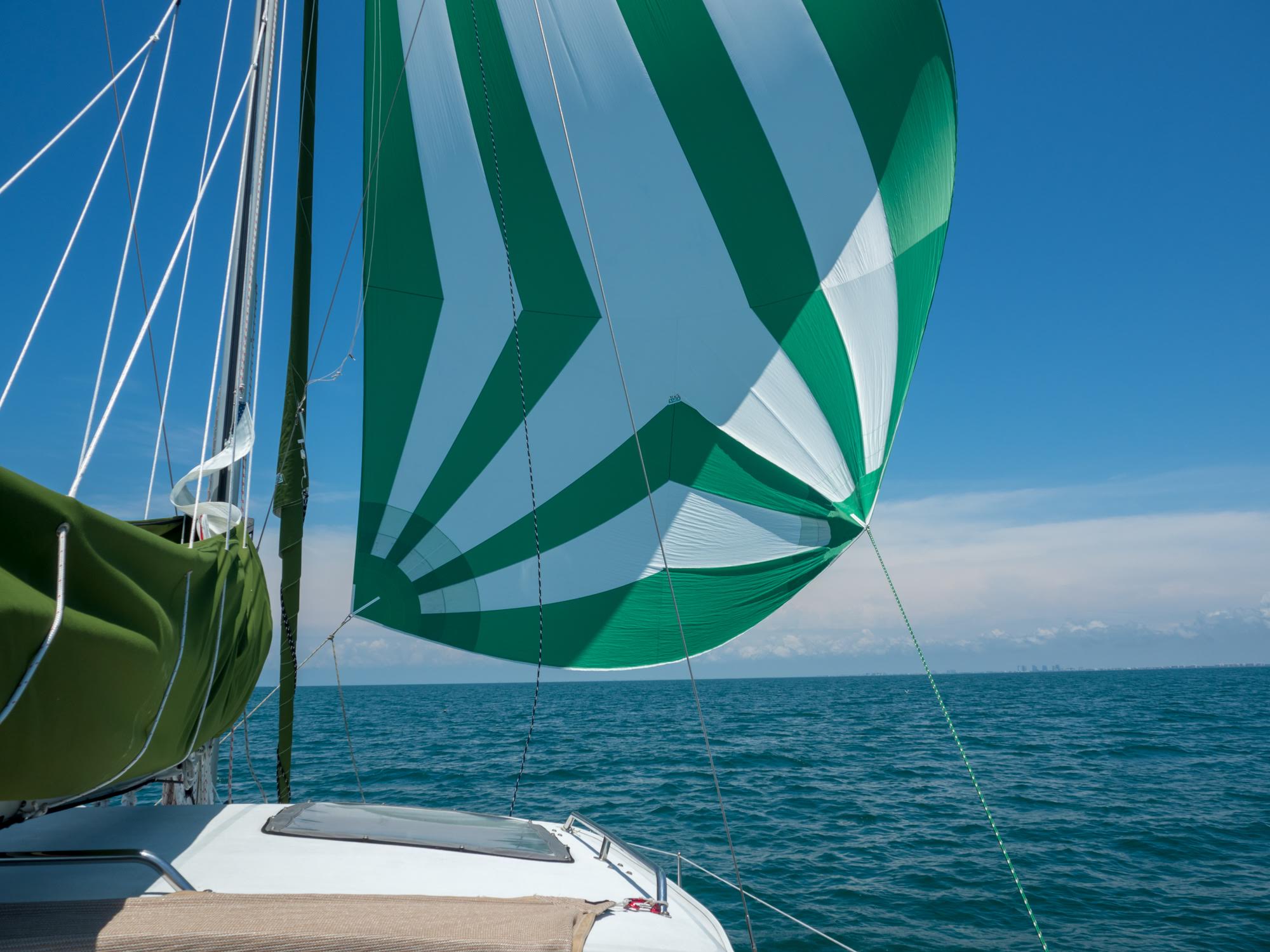
When I purchased new sails for Terrapin, I also bought a spinnaker. The spinnaker is used for downwind sailing when the wind is between 90 and 180 degrees off the bow. Paradoxically dead downwind sailing or “a run” is generally one of the slowest points of sail, mainly because you are relying on your sails to be “pushed” by the wind directly behind them. Conventional main and jib are not really designed for this. Instead, conventional sails are designed to be a curved airfoil, like a vertical airplane wing. The wind passing over the front of the sail provides “forward lift” and propels the boat forward. In some cases, this can propel the boat faster than the wind speed as in the recent Americas Cup catamarans. The spinnaker is a large light balloon like sail that catches the maximum amount of wind from behind to improve downwind sailing performance. It is generally used for light wind of less than 15 knots.
The spinnaker is also somewhat tricky to rig and deploy and I had no experience with them other than reading and watching YouTube videos. We have been on several stretches of long downwind sailing on Terrapin during our recent cruise to the Keys and have been frustrated with the slow speed. Finally, one day I decided to test out the new spinnaker. I think I made every mistake in the book and paid the price. With Laura at the helm, I went to the bow and pulled the spinnaker out of the bow locker. It is in a rather large bag and pretty unwieldly. I hooked it up to a bridle that ran from one bow to the other with a shackle to attach to one of the lower corners of the spinnaker, called the tack. The other lower corner of the spinnaker is called the clew and is where you attach the sheet that runs to the cockpit on the leeward side and controls the shape of the sail. By adjusting both the bridle position side to side and the sheet, I can control the position of the spinnaker and the amount of “ballooning”, or so goes the theory. The spinnaker is in a sock about 40’ long and designed to be raised and unfurled in two steps: 1. Attach the head of the sail to the spinnaker halyard and hoist it up to the top of the mast. 2. Pull on another line running from a cuff around the bottom of the sock to the top of the spinnaker and then back down again. Pulling on this line raises the sock and allows the lightweight nylon spinnaker to unfurl and catch the wind. To douse the spinnaker, you pull the sock back down with the same line. So, I hooked up the tack and clew and raised the sock on the halyard. So far so good. Except that by the time I had done all this, the wind speed had increased to about 15k, gusting to 20. I should have stopped right there. Hindsight is 20/20, right? Well, I raised the sock and all hell broke loose. The sheet running to the cockpit wasn’t secured and came loose, allowing the spinnaker to flap uncontrollably in the strong wind. It started to wrap around the forestay where the genoa is rolled up on a roller furler. I had also left the two genoa sheets attached to the genoa and these quickly became tangled with the spinnaker lines. I tried to bring the sock down but it was jammed. I spent what seemed like an eternity trying to control this crazy flapping spinnaker, but it was probably about 10 minutes. I finally went to the mast and lowered the halyard lowering the whole mess to the trampoline. Exhausted.
Lessons learned:
Don’t try to fly the spinnaker in wind stronger than 15 knots, at least until you have plenty of experience.
Attach the sheet and tack more securely.
Make absolutely sure the sock is free and clear of all lines and on the proper (leeward) side the forestay.
Remove the genoa or jib sheets so there is no chance of getting tangled
Clear the deck of all stuff, fenders, docklines, etc.
Practice with raising the spinnaker at the dock before attempting to use it under sail.
Well, after digesting and re-enacting the scenario in my mind, I finally got the courage to try it again when we were sailing downwind in much lighter wind. This time it worked perfectly! What a good feeling to pull up the sock and see this beautiful sail catch the wind and feel the boat accelerate.